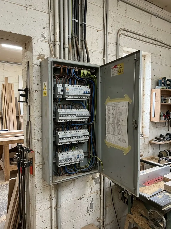
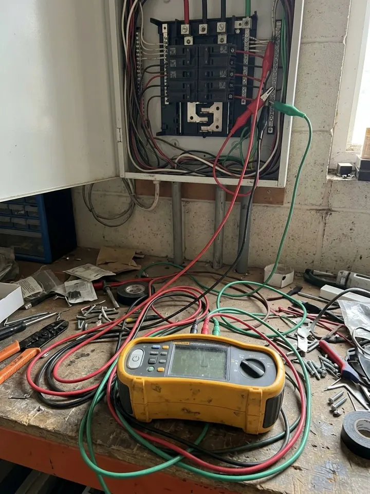
An electrical test sheet for a distribution board. Record the supply, Ze or Zdb and prospective fault current and photos of the board, then each circuit with its protective device, cable sizes, continuity and ring readings, insulation resistance, polarity, measured and maximum Zs, RCD time and the test button. The form works out Ze + (R1 + R2) as a cross-check on the measured Zs, (r1 + r2) / 4 for a ring, and the measured Zs as a share of the maximum you enter from the BS 7671 tables or the manufacturer. It warns on insulation resistance under 1 MΩ at 500 V, Zs over the maximum and an RCD slower than 300 ms, flags a pass that does not match the readings, and counts circuits passed, failed and outside each limit. It is a site record of the readings, not the BS 7671 schedule itself. Try the form below, see every question or open a completed example.
✎Every question is editable. Add this form to your account, then change the wording, add or remove questions and options, and make it fit your own jobs.
A schedule of test results records, for each circuit on a board, the circuit number and description, the protective device type and rating, the live and protective conductor sizes, continuity (R1 + R2, and r1, rn and r2 for a ring), insulation resistance live to live and live to earth with the test voltage, polarity, the maximum measured earth fault loop impedance Zs, the RCD disconnection time and the test button checks. The IET model schedule for BS 7671:2018+A4:2026 has these columns.
Record the board and supply, then each circuit's readings. The form works out Ze + (R1 + R2) and (r1 + r2) / 4 as cross-checks, shows the measured Zs as a share of the maximum you enter from the BS 7671 tables, warns on readings outside the limits it checks and counts circuits by result. It is a site record of the readings, not the BS 7671 schedule itself.
Circuits counted against each limit
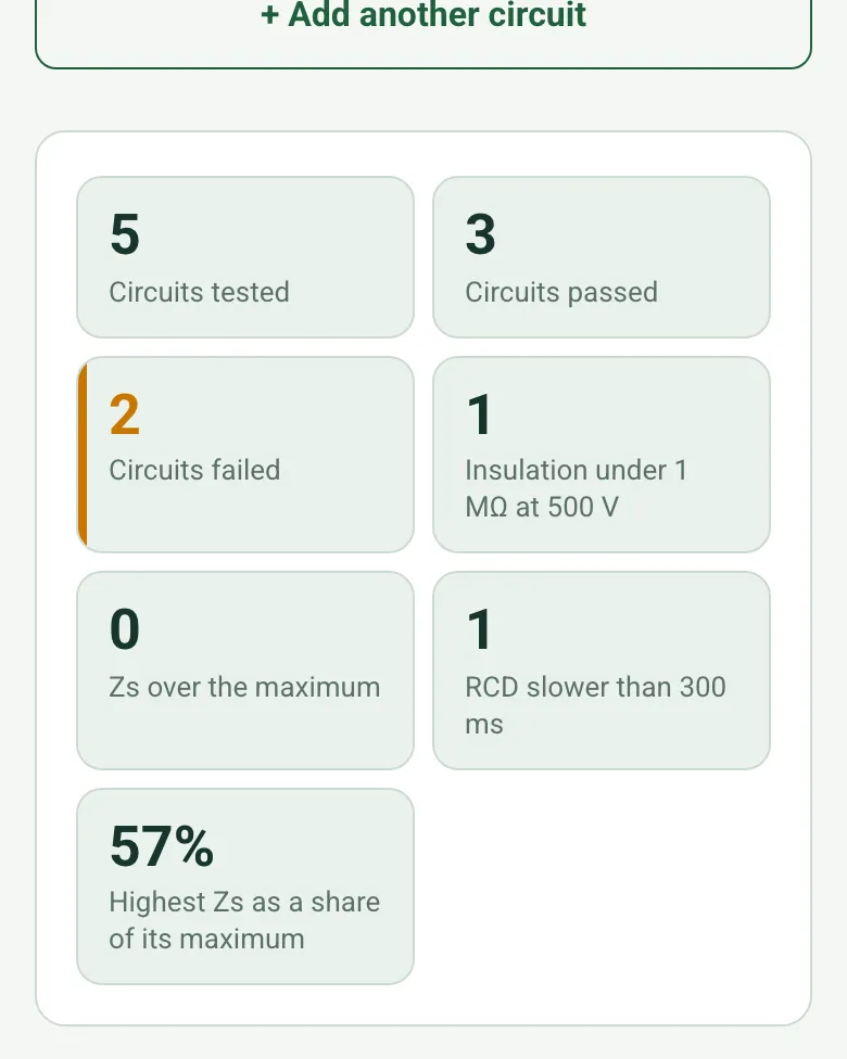
The form counts circuits tested, passed and failed, with insulation resistance under 1 MΩ at 500 V, Zs over the maximum entered and an RCD slower than 300 ms, and shows the highest Zs as a share of its maximum.
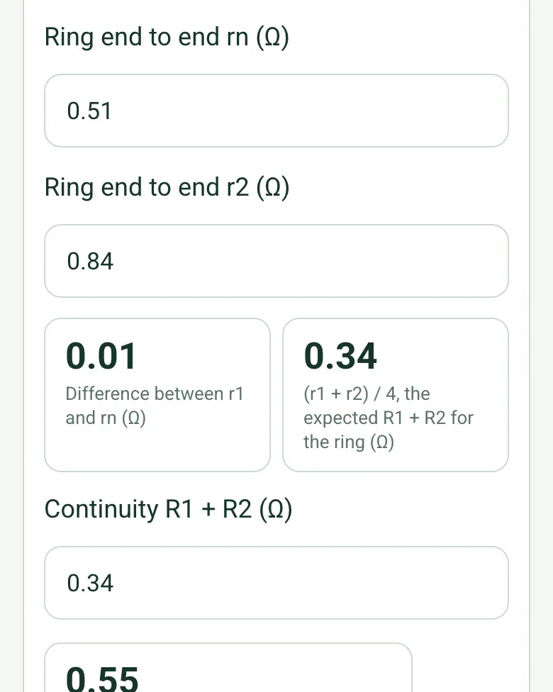
For a ring final circuit, the form shows the difference between r1 and rn and works out (r1 + r2) / 4, the R1 + R2 you would expect at each socket, next to the reading you take.
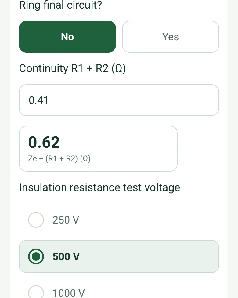
From Ze or Zdb on page 1 and R1 + R2, the form works out Ze + (R1 + R2), a common cross-check on the measured Zs, and the measured Zs as a share of the maximum.
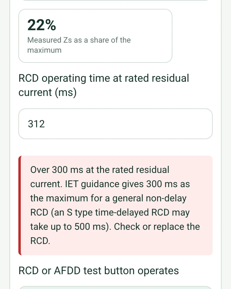
An RCD over 300 ms at its rated residual current, insulation resistance under 1 MΩ at 500 V or Zs over the maximum brings up a red note, and a circuit marked as a pass with one of these gets an amber note.
Add photos of the board with its cover on and off, or a Walk Cam recording with spoken notes, so the record shows the board you tested.
A completed schedule of test results
A fictional joinery workshop board: five circuits, a ring with matching end to end readings, a dust extractor radial with 0.6 MΩ to earth left off and labelled, and a yard lighting RCBO that took 312 ms, recorded as a fail with a replacement booked.
This is the real form as your team would use it: questions appear as you answer, scores work themselves out and you can add photos and signatures. No sign-up needed. Or open a completed example to see every answer, photo and score filled in.
Every question in the schedule of test results template
An electrical test results schedule for a distribution board: every circuit with its device, cables, continuity, insulation resistance, polarity, Zs and RCD times, with warnings on readings that fail. 3 sections and 61 questions. Follow-up questions and guidance appear only when an answer calls for them, so the person on site never sees the ones that do not apply.
✎
Make it your own: every question is editable
This is a starting point, not a fixed form. Once it is in your SiteSurvey account you can reword any question, add or remove questions, sections and answer options, and add your own logo, so it fits the way your team works and the jobs you do.
Details you only enter once
Add this form to a project in SiteSurvey and it fills in what the project already knows, so nobody on site retypes it and every form on the job uses the same names. Anything filled in can still be changed.
Project: the project name
Client: the project's customer
Site: the site, when the form is opened for a space or a product
Site address: the site address, from the space or the project
1
Board and supply
ProjectShort answer
Fills in from the project name
ClientShort answer
Fills in from the project's customer
Site*Short answer
Fills in from the site, when the form is opened for a space or a product
Site addressShort answer
Fills in from the site address, from the space or the project
Date of the tests*Date
Tested by*Short answer
Distribution board reference and location*Short answer
Scan the board labelScan a label: asset number
Optional. Scan the label or tag to capture its numbers.
Photos of the boardPhotos
Optional. The board with its cover on and off, the circuit chart and anything you found.
Earthing arrangementChoose one
TN-C-S (PME)
TN-S
TT
Other
Earth fault loop impedance at the board, Ze or Zdb (Ω)Number
Ze at the origin, or Zdb at a sub-distribution board.
Prospective fault current (kA)Number
Test instrument, serial number and calibration dateShort answer
CheckThis is a site record of the readings and checks. It is not the BS 7671 certificate or schedule itself: issue that from your registration scheme's or your certification software.
2
Circuits
Circuits tested
Repeat for each circuit. Each one asks:
Circuit number*Short answer
Circuit description*Short answer
Points servedNumber
Live conductor (mm²)Number
Protective conductor (mm²)Number
Protective deviceChoose one
MCB type B
MCB type C
MCB type D
RCBO type B
RCBO type C
BS 88 fuse
BS 1361 fuse
BS 3036 rewireable fuse
Other
Rating (A)Number
RCD typeChoose one
Type AC
Type A
Type F
Type B
No RCD
Ring final circuit?Yes or No
Ring end to end r1 (Ω)Number
Shown when “Ring final circuit?” is Yes
Ring end to end rn (Ω)Number
Shown when “Ring final circuit?” is Yes
Ring end to end r2 (Ω)Number
Shown when “Ring final circuit?” is Yes
Difference between r1 and rn (Ω)Worked out by the form
Shown when “Ring final circuit?” is Yes and “Ring end to end r1 (Ω)” is answered and “Ring end to end rn (Ω)” is answered
(r1 + r2) / 4, the expected R1 + R2 for the ring (Ω)Worked out by the form
Shown when “Ring final circuit?” is Yes and “Ring end to end r1 (Ω)” is answered and “Ring end to end r2 (Ω)” is answered
Continuity R1 + R2 (Ω)Number
Ze + (R1 + R2) (Ω)Worked out by the form
Ze or Zdb from page 1 plus R1 + R2. Compare it with the measured Zs below.
Shown when “Earth fault loop impedance at the board, Ze or Zdb (Ω)” is answered and “Continuity R1 + R2 (Ω)” is answered
Insulation resistance test voltageChoose one
250 V
500 V
1000 V
Insulation resistance, live to live (MΩ)Number
Insulation resistance, live to earth (MΩ)Number
WarningBelow 1 MΩ. The IET gives 1 MΩ as the minimum insulation resistance, with a 500 V d.c. test for circuits up to 500 V. Investigate before the circuit is put into service.
Shown only when the answers above make it relevant
PolarityChoose one
Correct
Fault
Earth fault loop impedance Zs, measured (Ω)Number
Maximum permitted Zs for this device (Ω)Number
From the BS 7671 tables or the device manufacturer.
Measured Zs as a share of the maximum (%)Worked out by the form
Shown only when the answers above make it relevant
WarningMeasured Zs is above the maximum permitted for this protective device. The device may not disconnect in time.
Shown only when the answers above make it relevant
RCD operating time at rated residual current (ms)Number
WarningOver 300 ms at the rated residual current. IET guidance gives 300 ms as the maximum for a general non-delay RCD (an S type time-delayed RCD may take up to 500 ms). Check or replace the RCD.
Shown only when the answers above make it relevant
RCD or AFDD test button operatesChoose one
Yes
No
Not fitted
Result*Choose one
Pass
Fail
CheckRecorded as a pass, but a reading above is outside a limit the form checks. Check the reading and the result.
Shown only when the answers above make it relevant
ObservationsNotes
Shown only when the answers above make it relevant
c_f_passWorked out by the form
c_f_failWorked out by the form
c_f_irWorked out by the form
c_f_zsWorked out by the form
c_f_rcdWorked out by the form
Circuit retest readingsAnswer
Only when the circuit failed: one row per retest after the fix. Limits: insulation 1 MΩ (500 V test), RCD 300 ms (general non-delay). For a 250 V SELV or PELV test or an S type RCD, judge the result yourself.
Shown only when the answers above make it relevant
Circuits testedWorked out by the form
Circuits passedWorked out by the form
Circuits failedWorked out by the form
Insulation under 1 MΩ at 500 VWorked out by the form
Zs over the maximumWorked out by the form
RCD slower than 300 msWorked out by the form
Highest Zs as a share of its maximum (%)Worked out by the form
Shown only when the answers above make it relevant
3
Actions and sign-off
Are further actions needed?Yes or No
CheckA circuit failed, but no further action is recorded. Add what needs doing, who will do it and when.
Shown only when the answers above make it relevant
Further actions
Repeat for each action. Each one asks:
Shown when “Are further actions needed?” is Yes
What needs doing?*Notes
Who will do it?Short answer
Due dateDate
StatusChoose one
Open
In progress
Completed
Inspector nameWorked out by the form
Position or company of the testerShort answer
Inspector signatureSignature
CheckSigning records what was found on the day. It is not a guarantee of condition and does not replace any examination, test, design check or repair needed from a competent person.
See it filled in
A completed schedule of test results report, made by SiteSurvey from a fictional site visit: every answer, the photos, the guidance that applied and the sign-off, ready to send as a PDF.
The IET gives 1 MΩ as the minimum insulation resistance, with a 500 V d.c. test for circuits up to and including 500 V (other than SELV and PELV). The form shows a warning when either reading at 500 V is under 1 MΩ, so the circuit is investigated before it is put into service.
How does it check Zs?
Enter the measured earth fault loop impedance and the maximum permitted for that protective device, from the BS 7671 tables or the device manufacturer. The IET schedule asks you to note the source when the maximum is not from the BS 7671 tables. The form warns when the measured value is higher, because the device may not disconnect in time. It also shows Ze + (R1 + R2) next to the reading as a cross-check, and the measured Zs as a share of the maximum.
What about RCD tests?
Record the operating time from an alternating current test at the rated residual current. IET guidance gives 300 ms as the maximum for a general non-delay RCD, and 130 to 500 ms for an S type time-delayed RCD. The form warns over 300 ms, and records whether the RCD or AFDD test button works.
Is this the BS 7671 schedule itself?
No. It is a site record of the readings, so they are captured on the phone with the board and circuit details. Issue the formal certificate and schedule from your registration scheme's or your certification software.
Can I record ring final circuits?
Yes. Answer that the circuit is a ring and the form asks for the end-to-end r1, rn and r2 readings as well as R1 + R2. It shows the difference between r1 and rn and works out (r1 + r2) / 4, the R1 + R2 you would expect at each socket on a sound ring.
Who uses this?
Electricians testing new work, periodic inspections and remedial work, and facilities teams keeping results for each board. In England, private and social landlords must have the electrical installation inspected and tested at least every 5 years, and the report includes a schedule of test results.